CAD Drawings
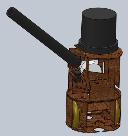
Our goal during the mechanical design process was to build the smallest robot possible, thereby permitting us to use a longer lance and maximize the chance of hitting our opponent. Furthermore, our strategy was to move back and forth away from the wall, ideally out of range of larger robots with shorter lances. As such, we needed appropriate sensing equipment in order to remain oriented in the middle of an open arena.
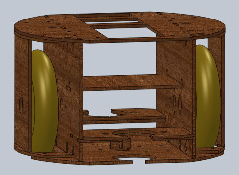
For easy of construction and integration, the upper and lower sections of the robot were built as separate assemblies which were later fastened together. Care was taken during the design of the lower section to keep the robot’s footprint as small as possible. The two drive motors were mounted as close together as possible, and the wheels were mounted on axles just long enough to provide adequate clearance from the frame. An even smaller wheelbase could have been achieved by placing the drive motors side by side. With this configuration, however, the axles would be out of alignment unless they were offset from the drive shafts via gears. Ultimately, we felt as though this minor reduction in size was not worth the complexity and the mechanical inefficiencies of a geared drivetrain.
For wheels we used roller blade wheels due to their convenience and fairly good grip. We used 110mm wheels, the largest available, because back of the envelope calculations told us that larger wheels, given our gear ratio, would allow us to move at higher speeds. Larger wheels also created more space under the axles to mount circuit boards.
In order to keep track of our position and orientation, we decided to attach encoders to the drivetrain. To keep size down, we did offset the encoders from the axles via gears. Unlike the wheels, the encoders exert virtually no load, so the mechanical inefficiency of gears was not a concern in this case. Although the encoders were quite accurate, the ability to recalibrate was desired. The front and back of the robot featured flat sections so that the robot could push itself into a wall and realign. Two tape sensors were also mounted on the underside of the body to detect tape.
We anticipated having to access the components in the lower half of the robot a number of times. To facilitate repeated assembly and disassembly of such a compact, densely packed device, the entire lower section was held together with fasteners as opposed to glue.
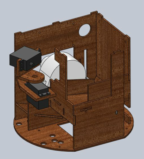
The upper half of the robot was based upon the same footprint as the lower half. Among circuit boards and other components, it housed the ball shooter, a ramp for the balls, and the lance mechanism. The ball shooter consisted of a spinning foam wheel which would catch the balls and shoot them forwards. The ball shooter was mounted above the balls so as to impart them with topspin.
Balls feed into the ball shooter via a ramp. The ramp was fairly circuitous in order to make room for all five balls within the small robot. A servo actuated gate was located at the end of the ramp to release balls into the shooter.
The lance mechanism consisted of two servo motors mounted in series. This configuration allowed us to sweep the lance side to side as well as up and down.
Unlike the lower assembly, the upper assembly did not require disassembly, so it was glued together. The E128, the JSR, and all circuit bolts, however, were bolted to standoffs so that they could easily be removed and modified if necessary.
For easy of construction and integration, the upper and lower sections of the robot were built as separate assemblies which were later fastened together. Care was taken during the design of the lower section to keep the robot’s footprint as small as possible. The two drive motors were mounted as close together as possible, and the wheels were mounted on axles just long enough to provide adequate clearance from the frame. An even smaller wheelbase could have been achieved by placing the drive motors side by side. With this configuration, however, the axles would be out of alignment unless they were offset from the drive shafts via gears. Ultimately, we felt as though this minor reduction in size was not worth the complexity and the mechanical inefficiencies of a geared drivetrain.
For wheels we used roller blade wheels due to their convenience and fairly good grip. We used 110mm wheels, the largest available, because back of the envelope calculations told us that larger wheels, given our gear ratio, would allow us to move at higher speeds. Larger wheels also created more space under the axles to mount circuit boards.
In order to keep track of our position and orientation, we decided to attach encoders to the drivetrain. To keep size down, we did offset the encoders from the axles via gears. Unlike the wheels, the encoders exert virtually no load, so the mechanical inefficiency of gears was not a concern in this case. Although the encoders were quite accurate, the ability to recalibrate was desired. The front and back of the robot featured flat sections so that the robot could push itself into a wall and realign. Two tape sensors were also mounted on the underside of the body to detect tape.
We anticipated having to access the components in the lower half of the robot a number of times. To facilitate repeated assembly and disassembly of such a compact, densely packed device, the entire lower section was held together with fasteners as opposed to glue.
The upper half of the robot was based upon the same footprint as the lower half. Among circuit boards and other components, it housed the ball shooter, a ramp for the balls, and the lance mechanism. The ball shooter consisted of a spinning foam wheel which would catch the balls and shoot them forwards. The ball shooter was mounted above the balls so as to impart them with topspin.
Balls feed into the ball shooter via a ramp. The ramp was fairly circuitous in order to make room for all five balls within the small robot. A servo actuated gate was located at the end of the ramp to release balls into the shooter.
The lance mechanism consisted of two servo motors mounted in series. This configuration allowed us to sweep the lance side to side as well as up and down.
Unlike the lower assembly, the upper assembly did not require disassembly, so it was glued together. The E128, the JSR, and all circuit bolts, however, were bolted to standoffs so that they could easily be removed and modified if necessary.